With RelativeFlow Blockage sensing, operators can see the flow of both seed and fertilizer from inside the tractor cab. Sensors on all secondary hoses monitor the relative product flow row to row, giving you a better view of the flow rate of both seed and fertilizer from the cart to the opener from inside your tractor cab. This technology can help you identify any problems before a potential blockage occurs.
RelativeFlow Blockage is available in all run configurations on the following models (all widths):
H500
H500F
P500
P600
N500
N500F
N500C
730LL
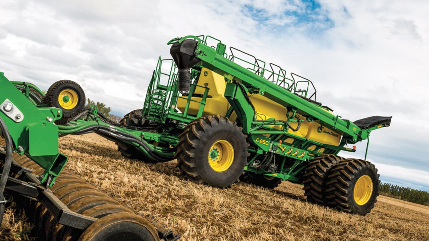
RelativeFlow Blockage is compatible with hydraulic drive carts: model year 2014 and newer 1910, all 19.381,5-L (550-bu) 1910 Carts, and C650 and C850 Air Carts.
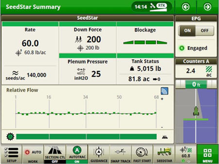
Below are the Gen 4 display screens for the blockage monitoring system. Consulte el manual del propietario para obtener detalles e información completa.
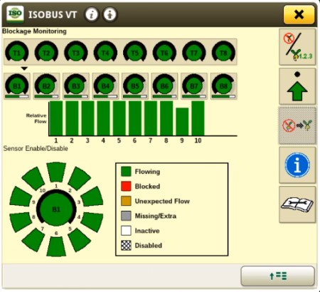
Blockage monitoring screen on Gen 4 display
The RelativeFlow Blockage sensing chart shows the amount of flow through each sensor on the selected tower. La sensibilidad del sistema de obstrucción puede ajustarse si lo desea, como se muestra a continuación.
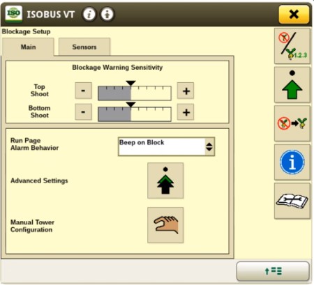
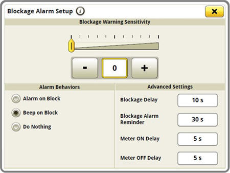
Blockage Setup screen on Gen 4 display
Blockage warning sensitivity allows the producer to set and change the sensitivity of the sensors to meet their preferences and varying crop/fertilizer types. Una mayor sensibilidad implica que es más probable que el sistema muestre una falsa obstrucción, mientras que con una menor sensibilidad, es más probable que el sistema pase por alto la obstrucción.
Se pueden seleccionar múltiples opciones de funcionamiento para la alarma en la página de ejecución.
Blockage monitoring screen on Gen 4 display
Below are the Gen 4 display screens for the blockage monitoring system on the N500C.
For complete details and information reference, the owner’s manual.
RelativeFlow Blockage configured run page
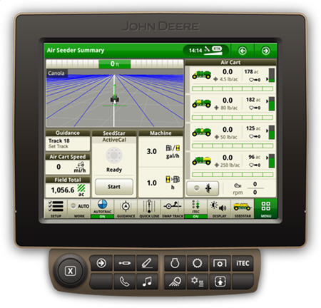
The SeedStar™ system run page displays the five major run settings. Clicking on any of the tiles will take an operator to that specific page (shown below).
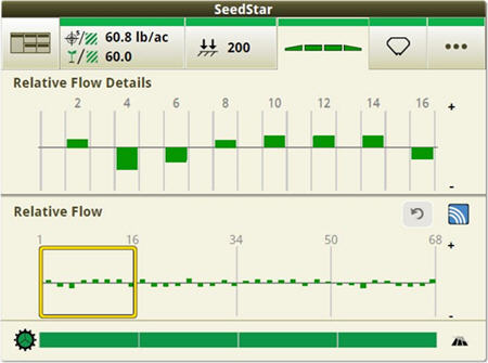
Operators can zoom into flow details by meter section when selecting blockage tiles
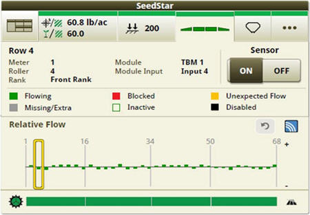
Operators can zoom into the row level to access row/sensor information and turn a sensor on/off independently
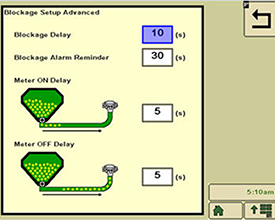
Blockage sensitivities and alarm delays are all set up on one easy-to-navigate screen
Los retrasos en la alarma de obstrucción se pueden configurar haciendo clic en el botón de configuración avanzada de la pantalla de configuración de obstrucción.
Una demora refiere al tiempo que debe transcurrir antes de que suene la alarma por una obstrucción.
Un recordatorio de la alarma de obstrucción establece la frecuencia con la que debe sonar la alarma cuando ocurre una obstrucción.
La demora en el encendido del medidor refiere al tiempo desde que se enciende el medidor hasta que el sensor de obstrucción debe comenzar a monitorear.
La demora en el apagado del medidor es el tiempo desde que se apaga el medidor hasta que el sensor de obstrucción debe comenzar a monitorear para verificar que no haya ningún caudal.
Consulte el manual del propietario para obtener más detalles.
Air tools with RelativeFlow Blockage are not compatible with 1910 air carts with ground drive.
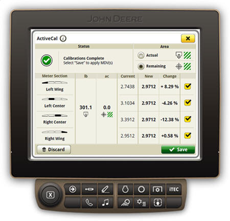
The more frequently calibration is completed, the more accurate a seeder will be. A number of variables, including product weight and changing climate conditions throughout the day, will have an effect on any volumetric metering system; with the John Deere ActiveCal system, calibration can be done from the cab of the tractor, while seeding, to minimize the variation in product metering.
The process to calibrate the implement starts with the Gen 4 4600 CommandCenter™ Display in the work setup page, where the operator defines product types, rates and selects meter rollers. Based on information entered into the work setup page, a preconfigured meter displacement value (MDV) will populate per meter. An initial manual calibration will give the most accurate MDV to start with. However, the preconfigured MDV will be a good starting point for growers who do not wish to manually calibrate.
The operator engages ActiveCal while stationary by selecting the button on the screen and then begins seeding. When enough product has been metered out, typically after about 3,2 to 4,9 ha (8 to 12 acres), the Gen 4 CommandCenter will prompt the operator to stop when convenient to do so. At that time, the data points are calculated and a new MDV with percent difference is displayed on screen. The operator can accept or reject the new MDV. If accepted, the system automatically calibrates to the new MDV. If rejected, the system continues at the previously calibrated numbers.
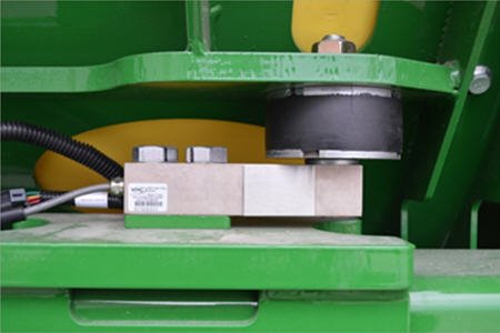
Tank scales provide tank weights to ActiveCal system
A meter cartridge at each tank effectively meters seed or fertilizer into the primary manifold. Air carries the material to the secondary distributor for delivery to the openers on the seeding tool.
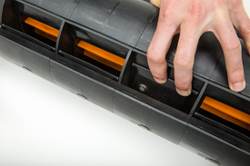
Meters are contained in a cartridge for convenient removal and are color coded for easy identification.
Metering system
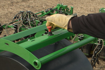
A manual half-width disconnect is incorporated into the meter system:
Allows one-half of the metering system to be manually shut off for irregular shaped headlands, point rows, etc. on mechanical drive carts.
Allows the meter cartridge to be removed with material still in the tank(s).
Allows tanks to be emptied with meter and primary manifold in place.
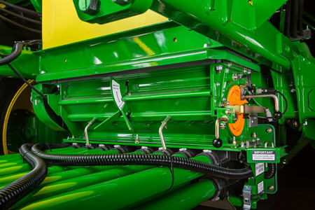
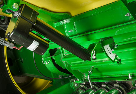
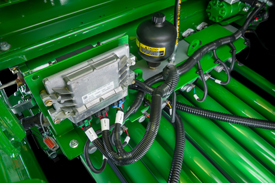
Electric actuator on C-Series Air Carts
On the C-Series Air Carts, an electric actuator controls product flow from the tank to the meter housing:
Allows complete shut off of product flow with little effort
Allows the meter cartridge to be removed with material still in the tank(s)
Allows tanks to be emptied with meter and primary manifold in place
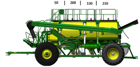
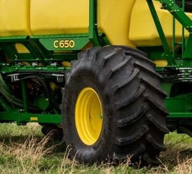
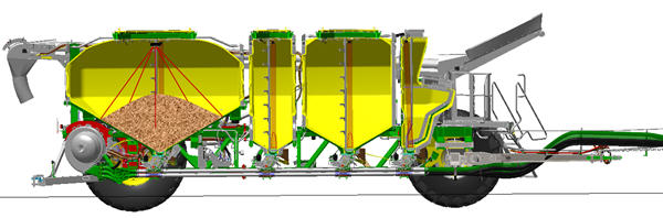
The total capacity of the C650 is 22.905 L (650 bu), measured by conveying product into the tank. The front tank is dedicated for low rate applications and holds 1762 L (50 bu). The remaining three tanks in order of front to rear are 9162 L (260 bu), 4581 L (130 bu), and 7400 L (210 bu).
John Deere air cart tanks are solid molded polymer, known for superior corrosion resistance compared to steel while providing semi translucency allowing for visual verification of product level in day-time operation. Each tank is mounted in a cradle frame to eliminate interference between each other. The polymer material does not require weldments like on steel tanks. Weldments on steel tanks are prone to failure over time as the metal is fatigued under stress.
The improved top bevel design on tanks allow for greater capacity and meets the 22.905 L (650 bu) capacity without the need for shoveling product into the corners while conveyor filling.
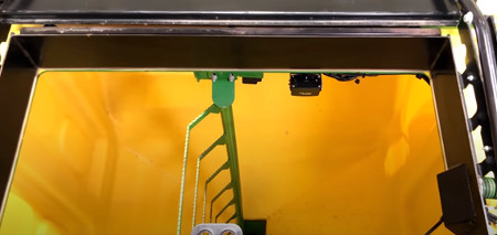
Each tank has a wide, single opening, which means it is easy for access for the conveyor and entry to the tank. Inside each tank is a ladder for cleanout access. Ladders in the tanks have been designed so that material cannot build up on steps. Top rails have been capped and sloped to ensure product sheds from the surface. When cleaning out the cart, the tanks slope steeply at bottom for product to flow easily and each tank is accessible for fill and cleanout with the conveyor.
Tanks come equipped with digital pressure sensor, ultrasonic bin level sensing, and camera-ready harnesses mounted from the factory.
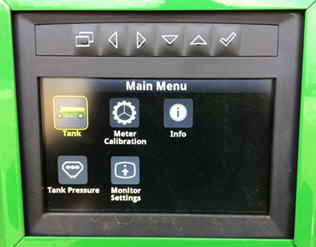
The durable display on the side of the cart will make filling and calibration easier than before. Selecting the menu button on the far left will take the grower to the main menu where they can select:
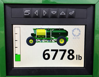
Tank: shows product weight and tank fill level
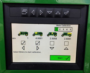
Meter calibration: preform a bag calibration without going back and forth to the cab to make inputs on the Gen 4 CommandCenter™ display
Info: shows display and software information
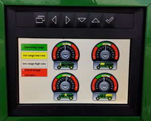
Tank pressure: shows the differential pressure between the tank and the meter for each individual tank
Monitor settings: allows the customer to adjust the brightness of the display
Tank screen
Tank weights and bin level will be shown on the first screen when the display is powered on. Navigating from one tank weight to another will be done by pressing the left and right arrow buttons.
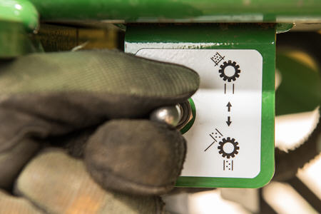
Meter calibration screen
Meter calibration can be done cart side. To select the tank or tanks that need to be calibrated, press the display button that matches the icon below the respective tank on the screen.
Tank pressure screen
The digital screen replaces the mechanical tank pressure gauges on previous carts.
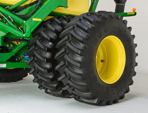
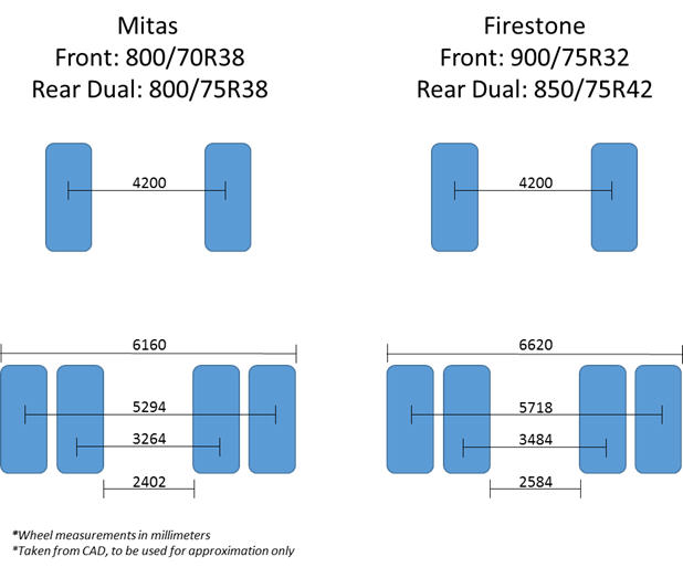
The tow-behind C650 Air Cart comes equipped with rear dual Firestone® 800/70R38 SFT tires and front single Firestone 900/75R32 CFO tires. The tow-between C650 comes equipped with rear dual Firestone IF850/75R42 CFO tires. These are high-floatation, low-compaction solutions. The Firestone tires run at an inflation pressure of 131 kPa (19 psi). Super flexion tire (SFT) technology means that the sidewalls on the tire are developed with additional reinforcement and superior rubber compounds, which enables the tires to run at a very low pressure while under higher loads without damaging the sidewalls. By running at lower pressure, the tire can flex its sidewalls and squat, allowing for a much wider footprint and improving floatation.
To see how the tire pressures on the C-Series Air Carts compare to the 1910 Commodity Carts, please reference the tire pressure guide.
Wheel measurements in mm
Mitas is a trademark of Mitas, Akciova Spolecnost Corporation. Firestone es una marca registrada de Bridgestone Americas Tire Operations, LLC.
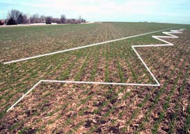
SectionCommand is an effective, integrated, exclusive John Deere solution that reduces costly overlaps and skips that can waste seed and fertilizer, while offering more consistent fields that improve the potential of your yield and your bottom line.
Thanks to individual meter sections that control commodity flow, you can maintain the right application rates and row-to-row accuracy. This helps stimulate even crop emergence during the growing season and promotes consistent crop maturity at harvest. SectionCommand controls output from all meters on the cart up to eight sections.
Owner benefits include:
Improved consistency of crop maturity at harvest
Improved consistency during emergence and growing season
Reduced seed input cost
Reduced fertilizer input cost
Increased time between fills due to input savings
SectionCommand is base equipment with optional deduct on all John Deere 1910 and C-Series Air Carts. Each tank and meter will receive SectionCommand components. A two-tank cart will control sections out of both tanks, a three-tank cart will control sections out of all three tanks, and the C-Series Air Carts will control sections out of all four tanks. SectionCommand is also available as an attachment for field conversion (AFC) for all 1910 hydraulic drive carts. See AFC kit story for more information.
SectionCommand controls seed and fertilizer output by closing and opening gates on the bottom side of the meter. When the gates are open, commodity is metered out, and when closed, commodity stays and continues to rotate within the meter. The meter stays full at all times so immediately when the gate opens, the commodity can flow into the primaries and out to the tool. Since each meter section has its own gate, application rates and row-to-row accuracy are not compromised. The gates are utilized to control commodity output on all sections. Once the last gate needs closed, the entire meter will stop turning, stopping product flow.
Seeded fields photo
When commanded, electric over-hydraulic solenoids engage actuators to instantaneously close the gate for the needed section. The actuators are powered via hydraulics from the same circuit as the hydraulic drive motors. When power is cut, oil is diverted to retract the actuators and open the gates. The retraction is both powered and spring assisted, so it will always default to the seeding position. The oil from SectionCommand drains back through the fan motor case drain line and is coupled with an accumulator on the valve block to provide extra drainage capacity.
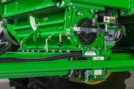
SectionCommand components as seen on back side of meter
SectionCommand components as seen on front side of meter
SectionCommand incorporates gate detection, which gives producers the satisfaction of knowing the gates are in position as commanded. Magnets on the back side of the gates are used in close proximity to the gate detection sensors to determine if the gates are open or closed. Should a gate not be in the commanded position, an alarm will alert the operator of the gate(s) in question. The blockage warning system works in conjunction with SectionCommand to give further confidence whether a given section is seeding or not when commanded.
SectionCommand meter cartridge showing one gate closed and magnet on backside of gate
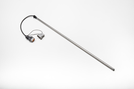
Gate detection sensor
For maximum performance, SectionCommand should be controlled through John Deere Section Control. Coupling SectionCommand with John Deere Section Control provides the ultimate in precision seeding and productivity. If a Section Control activation is held by the producer, that same activation can be utilized for SectionCommand.
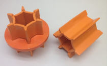
SectionCommand introduces the orange roller, which has the same number of flutes and spacing as the blue roller, but shorter flutes. It is for use only with SectionCommand when seeding seeds larger than 6 mm (0,25 in.) in diameter (soybeans, chick peas, etc.). The orange roller is not for use with cereal grains or fertilizer.
Orange roller for use only with large seeds and SectionCommand
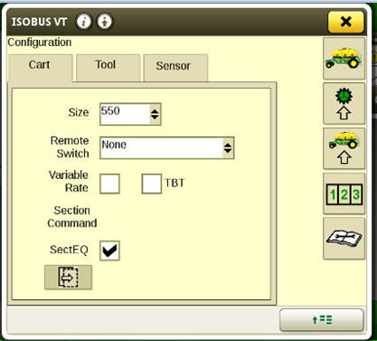
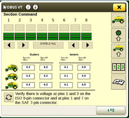
SectionCommand equalizer
Due to the varying lengths of product delivery hose used across the drill, SectionCommand has a built-in equalizer feature to ensure consistent product delivery across the width of the drill when entering and exiting headlands. The software allows the producer to set the on/off product delivery times separately for the outermost opener and the innermost opener on the drill. Product delivery times are inputted for each tank on the cart, and the software creates a time delay for actuation of the gates.
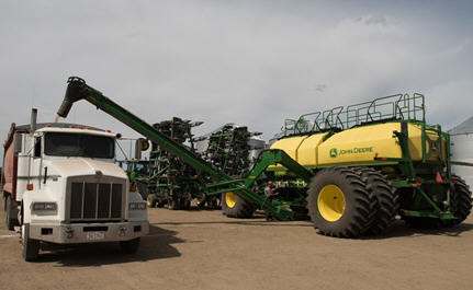
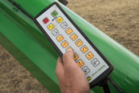
The C650 Air Carts come standard with the wireless-controlled hydraulic conveyance system with a low-profile hopper. Maneuvering the conveyor can be done from the wireless conveyor remote or the remote tethered to the cart. With five pivot points on the arm, all tanks can be filled from one spot. The pivot points also allow the conveyor to be easily positioned and moved when filling from a seed tender.
This conveyor moves up to 3524 L (100 bu) of product in a minute with a 48,26-cm (19-in.) belt inside the 30,5-cm (12-in.) tube. By moving the hopper under meter, the conveyor can be used for clean out on each tank as well.
Remote to operate conveyor
Conveyer shut off switch
The shut-off switches on the conveyor are located at the bottom of the tube, above the hopper and at the top of the conveyor near the spout. Filling at night is easy with the light-emitting diode (LED) 900-lumen lights on the cart and conveyor conveniently placed to illuminate each meter, the stairway and platform.
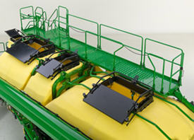
The C650 Air Carts have five tank lids to make filling convenient and quick. The three back tank lids are operated by pushing forward on the foot pedal and straight down on the handle. The lid slides out of the way, contouring the shape of the tank, so it does not interfere with the conveyor. The tank lids seal tight by pulling upward on the handle and stepping back on the foot pedal. The three back tank lids offer a wide opening, making an easy job out of placing the conveyor in the right place during fills. The design is a single per tank design, providing for faster fill times.
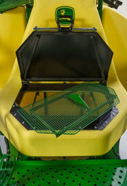
Bottom tank lid and bag splitter on front tank
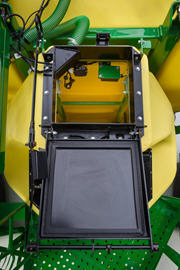
Top tank lid of front tank
The front 1762-L (50-bu) tank has two options to make loading low rate products easier. If the grower is filling the tank with bags, the front lid is accessible from the lower platform of the cart. The two front railings of the cart can be removed to allow for a truck to bring bags directly to the platform. As pictured above, the bottom fill location of the front tank has a bag splitter.
To fill the front tank with a conveyor, the top tank lid is easily reached with the hydraulic conveyance system.
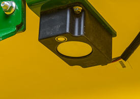
Ultrasonic waves are reflected off product in the tank
The John Deere ultrasonic bin level sensing system will increase the accuracy of bin level read outs in the cab and on the cart side display compared to the paddle design. The accuracy of this system is within 10 percent of actual product in the tank. Product in the tank is measured utilizing high-frequency sound waves (ultrasonic) that are emitted from the unit and received back when they reverberate off the product in the tank. These sound waves generate a digital signal which can be mapped across the angle of repose for the product in the tank. Using calculus volume can be determined from the convex slope determined from the ultrasonic frequencies. When metering two products into one airstream, ultrasonic can improve the accuracy of detection up to 50 percent more than traditional paddle sensors.
Monitoring product levels in tanks has never been easier with the camera-ready feature of C-Series Air Carts. The carts come pre-wired to accept a camera in each tank and one off the rear of the machine. Monitoring product levels is especially reassuring when product levels are low. Cameras also provide the operator with visibility behind the cart when traveling down the road or backing into a shed.
Camera locations on the C-Series Air Cart
Camera location on the C-Series Air Cart
For C-Series Air Carts, the producer can add up to five Voyager® or CabCAM™ cameras while also using a Generation 4 4600 CommandCenter™ Display or 4640 Universal Display. If the producer wants to view more than four cameras, a producer-purchased camera display will be needed.
NOTE: Generation 4 displays support Voyager and CabCAM cameras.
While the C-Series Air Carts come pre-wired to adapt cameras, additional harnesses are necessary for connecting to the tractor, and a tool overlay harness will be needed. Please use the part numbers below for configuring an existing, compatible tool.
Air cart model/configuration
Pantalla
Mazo de cables para la pantalla
Display harness to air cart/seeder or tool overlay harness
Seeding tool overlay harness
CabCAM adapter
Notas
C650/C850
Tow Behind
CommandCenter 4600
AA93727 (one
per camera) connected behind rear cab cover
AA94316
AA94564
Not required for Gen 4 display
Up to four CabCAM or Voyager cameras can be installed (four in tank, one rear view)
C650/C850
Tow Behind
Pantalla Universal 4640
SWTY268456
AA94316
AA94564
Not required for Gen 4 display
Up to four CabCAM or Voyager cameras can be installed (four in tank, one rear view)
C650
Tow Between
CommandCenter 4600
AA93727 (one per camera) connected behind rear cab cover
AA94316
Not required for Gen 4 display
Up to four CabCAM or Voyager cameras can be installed (four in tank, one rear view)
C650
Tow Between
Pantalla Universal 4640
SWTY268456
AA94316
AA97386
Not required for Gen 4 display
Up to four CabCAM or Voyager cameras can be installed (four in tank, one rear view)
CabCAM is a trademark of ATI Products, Inc. Voyager is a trademark of ASA Electronics, LLC.
Capacidad
Total
22905 L 650 bu
Configuración
Tow behind
Tow-behind
Conveyance
Rate
100 bu. per minute
Ancho de la correa
48,26 cm 19 in
Tube diameter
30,5 cm 12 in
Low profile hopper
183 cm X 76,2 cm X 23 cm 72 in. X 30 in. X 9 in.
Dimensiones
Largo
11,86 m 38 pies 11 pulgadas
Ancho
6,16 m 20 pies 2 pulgadas
Altura
Field - 16 ft. 3 in. (4,94 m) Transport - 13 ft. 4 in. (4,05 m)
Peso, vacío
16,59 kg 36.583 lb
Ventilador
Tracción
Hidráulico
Diámetro
69,85 cm 27,5 pulgadas
Air system type
B-type
Maximum rpm
550 lb. of seed per acre at 5,5 mph and 15 degree slope (300 lb. fertilizer and 250 lb. seed)
Air hose
Primary: Stainless-steel 3 in. (7,62 cm)
Neumáticos delanteros
estándar
Singles - Two IF 900/75R32 CFO Firestone (12 psi)
Especificaciones clave
Tipo de mando
Hidráulico
First tank capacity
1761 L 50 bu
Second tank capacity
9162 L 260 bu
Fourth tank capacity
7400 L 210 bu
Maximum rpm
550 lb. of seed per acre at 5,5 mph and 15 degree slope (300 lb. fertilizer and 250 lb. seed)
Peso, vacío
16,59 kg 36.583 lb
Third tank capacity
4581 L 130 bu
Metros
Tipo de mando
Hidráulico
Metering system
Five meter cartridges; 30 approved crops
Neumáticos traseros
estándar
Dual Tires and Rims 800/70R38 SFT Firestone (15 psi)
Complete este formulario para solicitar una cotización. Un representante lo contactará tan pronto como sea posible.
Gracias por enviarlo.
Solicitar un servicio
Complete nuestro formulario de solicitud para programar un servicio.
Gracias por enviarlo.
Solicitar partes
Complete nuestro formulario para solicitarnos una parte.
Gracias por enviarlo.
Solicite partes usadas
Complete nuestro formulario de solicitud para consultarnos sobre partes usadas.
Gracias por enviarlo.
Solicitar alquiler
Complete nuestro formulario para solicitarnos un alquiler.
Gracias por enviarlo.
Contáctenos sobre Precision Ag
Complete nuestro formulario para solicitar la tecnología Precision ag.
Gracias por enviarlo.
Contacto
Complete nuestro formulario de contacto y un representante se comunicará pronto con usted.
Gracias por enviarlo.
Conozca más sobre nuestros programas de servicio
Gracias por enviarlo.
Envíenos sus comentarios
¡Nos encantaría recibir sus comentarios! Complete el formulario a continuación para compartirlo.
Gracias por enviarlo.
Taller
Complete este formulario para contactarse con nuestro taller. Un representante lo contactará tan pronto como sea posible.
Gracias por enviarlo.
Solicitud de información sobre programas de capacitación técnica de Papé
Gracias por enviarlo.
Solicitud de técnico
Gracias por enviarlo.
Eventos, donaciones y patrocinios
Gracias por enviarlo.
Únase al equipo de Papé
Complete hoy nuestro formulario de empleo y un representante se comunicará con usted pronto.
Gracias por enviarlo.
Contacto
Complete nuestro formulario de contacto y un representante se comunicará pronto con usted.
Gracias por enviarlo.
¡Gracias por participar, usted es importante para nosotros! Complete la información de abajo y uno de nuestros miembros le ayudará lo más pronto posible.
Gracias por enviarlo.
Thank you for your interest in electrification, you are important to us! Please fill in your information below and one of our members will reach out to you as soon as we can.
Gracias por enviarlo.
Participación en el sorteo
Gracias por enviarlo.
Encuesta de estado de vacunación
Gracias por enviarlo.
Boletín general
Gracias por enviarlo.
Boletín de Hawái
Gracias por enviarlo.
Solicitud de transferencia de concesionario
Gracias por enviarlo.
Contacto
Complete nuestro formulario de contacto y un representante se comunicará pronto con usted.
Gracias por enviarlo.
Thank you for your interest in upgrading to a premium John Deere compact utility tractor. Please fill in your information below and a Papé Machinery member will contact you shortly.